A Probe That Images Is Not Yet an Accepted Probe
Same symptom on your system?
Tell us your model and what it is doing. A GEPROBE engineer replies with a diagnosis path, part options and pricing — usually within 6 hours, with no obligation.
Chat on WhatsApp
A VIVID E9 or VIVID E7 carries five probe ports on its console, and they are not five of the same thing. Section 3-5-6-1 of GE's service manual for the system (GB091046, Revision 2, p.3-21) sorts them into three types: one PD probe port, three PDT probe ports, and one Doppler probe port.
The difference is not cosmetic. The PD port is "compatible with the Vivid 7 probe connectors". The three PDT ports are "specific to the VIVID E9 / VIVID E7 probe connectors". The Doppler port is for CW Doppler probes, non-sector, which the same section also calls PEDOF probes.
So one console deliberately holds two connector generations side by side. That arrangement gives receiving inspection its first job, and it is rarely the job the receiving slip is built around. A probe that images on this machine has been shown to work in one port. It has not been shown to be in the right port, nor to belong to the connector generation that was ordered.
The manual's fitment requirement is an action, not a property
At the end of the pre-connection checklist in §1-4-4-2 (p.1-17), the manual writes: "The system has more than one type of probe port. Use the appropriate probe port designed for the probe you are connecting."
That sentence is addressed to the person holding the connector, which is where the decision has to sit, because nothing about the interface makes the decision for you. The connector either enters the port or it does not; the port does not know which generation the purchase order named. Fitment is settled before the connector reaches the console, by two documents: the purchase order, which names the model and its generation, and the manual, which names what each port accepts.
A clean image at handover therefore answers a narrower question than the receiving slip asks. It answers "does this probe produce a signal through this port", and it can answer that while the probe sits in a port it was never meant for.
| Port (count on the console) | What the manual says the port accepts | What a clean image still does not answer |
|---|---|---|
| PD port (one) | Vivid 7 probe connectors | Whether this probe is the generation this purchase ordered |
| PDT port (three) | Connectors specific to the VIVID E9 / VIVID E7 | Whether this probe falls inside the model range that port serves |
| Doppler port (one) | CW Doppler probes, non-sector (PEDOF) | Anything about sector or array probes |
Six checks before connection, six numbered steps to connect
§1-4-4-2 asks for six named points to be inspected before every connection, for "damage or degradation": the housing, the cable strain relief, the lens, the seal, the connector pins, and the locking mechanism.
The connection procedure is §3-5-6-2 (p.3-22), and it is numbered one to six. Step 1 splits into three parts.
- Before connecting the probe: a.) do a visual check of the probe pins and system sockets; b.) remove any dust or foam rests from the probe pins; c.) verify the probe and the probe cable for any visual damage.
- Hold the probe connector vertically with the cable pointing upward.
- Turn the connector locking handle counter-clockwise to the horizontal position.
- Align the connector with the probe port and carefully push into place.
- Turn the locking handle clockwise to the full vertical position to lock in place.
- Position the probe cable so that it is not resting on the floor.
Three cautions sit on the same page, and each one is a failure mode a receiving bench meets rather than a step in the sequence. "DO NOT ALLOW THE PROBE HEAD TO HANG FREELY. EXCESSIVE IMPACT TO THE PROBE WILL RESULT IN IRREPARABLE DAMAGE." "TO PREVENT PROBE CONNECTOR PINS DAMAGE, OR PCB BOARD DAMAGE, DO NOT USE EXCESSIVE FORCE WHEN CONNECTING THE PROBES." "KEEP THE PROBE CABLES AWAY FROM THE WHEELS. DO NOT BEND THE PROBE CABLES DO NOT CROSS CABLES BETWEEN PROBES."
Six damage points and six numbered steps describe a connection, and they are two different sixes: one list says what to look at, the other says what to do with the connector. Receiving slips tend to merge them into a single tick. They differ from an acceptance in exactly one respect: whether anything was written down. A check that leaves no line on a record does not survive the next shift, the next technician, or the next service organization.
What the returned probe should arrive carrying
Chapter 10 pushes probe cleaning and disinfection out to the user manual and puts two hard lines on the same page (§10-5-5-3 to §10-5-5-5, p.10-13). The lens must not be soaked or wiped with any product that is not listed for that probe. And: "Disinfect a defective probe before you return it. Be sure to tag the probe as being disinfected."
§1-4-4-2 closes the other half of it: "Never immerse the probe connector or adapter into any liquid."
Those two rules give the receiving desk its first two states to check, and both can be settled in seconds with the system switched off. The connector is dry. The probe is disinfected and carries a tag that says so. If either is untrue at arrival, the rest of the inspection has nothing to stand on.
Electrical safety supplies the third state. §10-6-1 (p.10-14) ties the test to NFPA 99 and IEC 62353 and requires a visual inspection before the measurement, one item of which reads: "Locate and examine all associated transducers. Inspect the cables and strain relief at each end. Inspect the transducer enclosure and lens for cracks, holes and similar defects." The interval named in the same section is "at least every 12 months".
That paragraph is worth a second reading at a receiving desk, because it treats the transducer as part of the system's electrical safety check rather than as an accessory attached to it. A probe that arrives with no record of that examination has not been shown to be safe to attach. It has been shown to be unexamined.
Three lines for the receiving slip
Line one is the port and the generation: PD, PDT or Doppler, and which specific port the probe was tried in. "Connected" names no port, so it cannot serve as this line.
Generation needs its own sentence here, because it is not a cosmetic attribute of a console. One model number on the front of a machine can carry two different lists of supported transducers once the software revision differs, and a probe supported on one console of that model can be unsupported on another — the pediatric phased array selection note works through a documented case of exactly that. At receiving the question is narrower: does this probe's generation match what the purchase order named, and the port it was tried in is the physical evidence for the answer.
Line two is the six inspection points, item by item, with a result against each. "Appearance normal" cannot carry this line. Housing and lens are two different findings, and an intact seal is not the same entry as a locking mechanism that turns freely.
Line three is the state at arrival: disinfected and tagged, or not; connector dry, or not. These are the two conditions the manual would have established before anything else is touched.
Two entries for the same probe differ by more than length. One reads "PDT port 2. Housing intact; strain relief uncracked at both ends; lens clear; seal seated; pins straight and free of residue; locking handle turns to vertical and holds". The other reads "probe OK, image good". The first can be held against the next arrival. The second records only that someone looked.
Three boundaries belong under those lines rather than inside them. None of the three lines proves acoustic performance; an element-level answer comes from an array test, and the line, test and threshold for element dropout is a separate examination with its own evidence. The leakage-current criterion moves with the applied-part class and with the test condition, so one pass at one setting is not a standing verdict, as the leakage-current reading and its conditions sets out. And an intermittent fault will usually appear on a receiving slip as "normal this time", because that is precisely what it did.
When the probe that looks wrong is the right one
The PD port exists to take the previous generation. A Vivid 7 probe seated in the PD port, imaging normally, can be a correct purchase rather than a mismatch. The mirror case is harder: a probe that belongs on a PDT port will look identical at handover if its connector happens to seat in the PD port and the image comes up.
The discriminator is not feel, not weight, and not "older than the one it replaced". It is the model on the purchase order against the sentence the manual writes for that port.
One honest limit on that. This 736-page manual states no mass for a probe at all. Table 3-11 gives the mass of the complete system with peripherals, and the other weight entries belong to the system, a single-person lift limit, the monitor and its gas spring. So "how many grams heavier than the last one" has nothing in this document to check against; comparing load means putting a like probe beside it, or asking the supplier for a written specification of the same generation.
What a receiving record buys is not this acceptance. It is the next exception — when the same probe images in a different port, or returns from service on a different connector, there is a line on file to hold the two readings against. Without that line every arrival is judged on its own, and an exception has no way to look like one.
Scope and limits: this is written for the people who receive probes — hospital equipment and biomedical engineering departments, and the goods-in side of independent service organizations. It is not a repair procedure and not clinical guidance. Every clause, page number and quotation above comes from one document, the GE VIVID E9 / VIVID E7 BT'13 service manual (GB091046, Revision 2); port assignments and inspection items for other manufacturers or other models do not follow from it. geprobe is an independent third-party supplier of probes and parts, and repairs them, with no affiliation, authorization or endorsement from any manufacturer named here. No prices appear in this article, and nothing here promises that any probe is available, repairable or compliant — whether a given probe can be used depends on its own test results and on the accepting organization's criteria, not on this page.
Related Articles
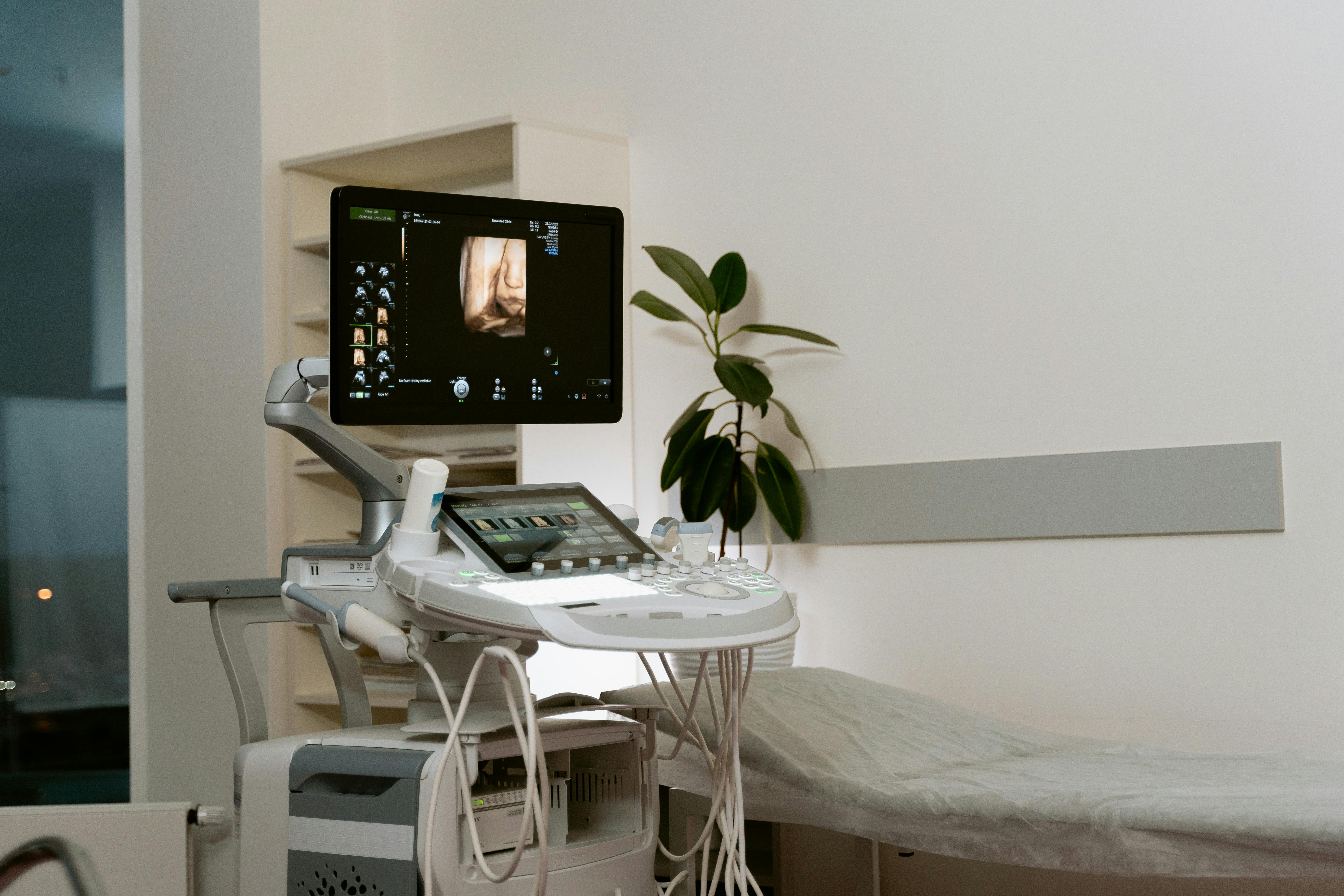
FDA MDR Component Codes: What an Ultrasound Service Record Has to Carry
A component code names the part that was involved, not the cause. What an ultrasound service record has to carry so that someone else can code the event - and what the service side should not decide for the reporter.
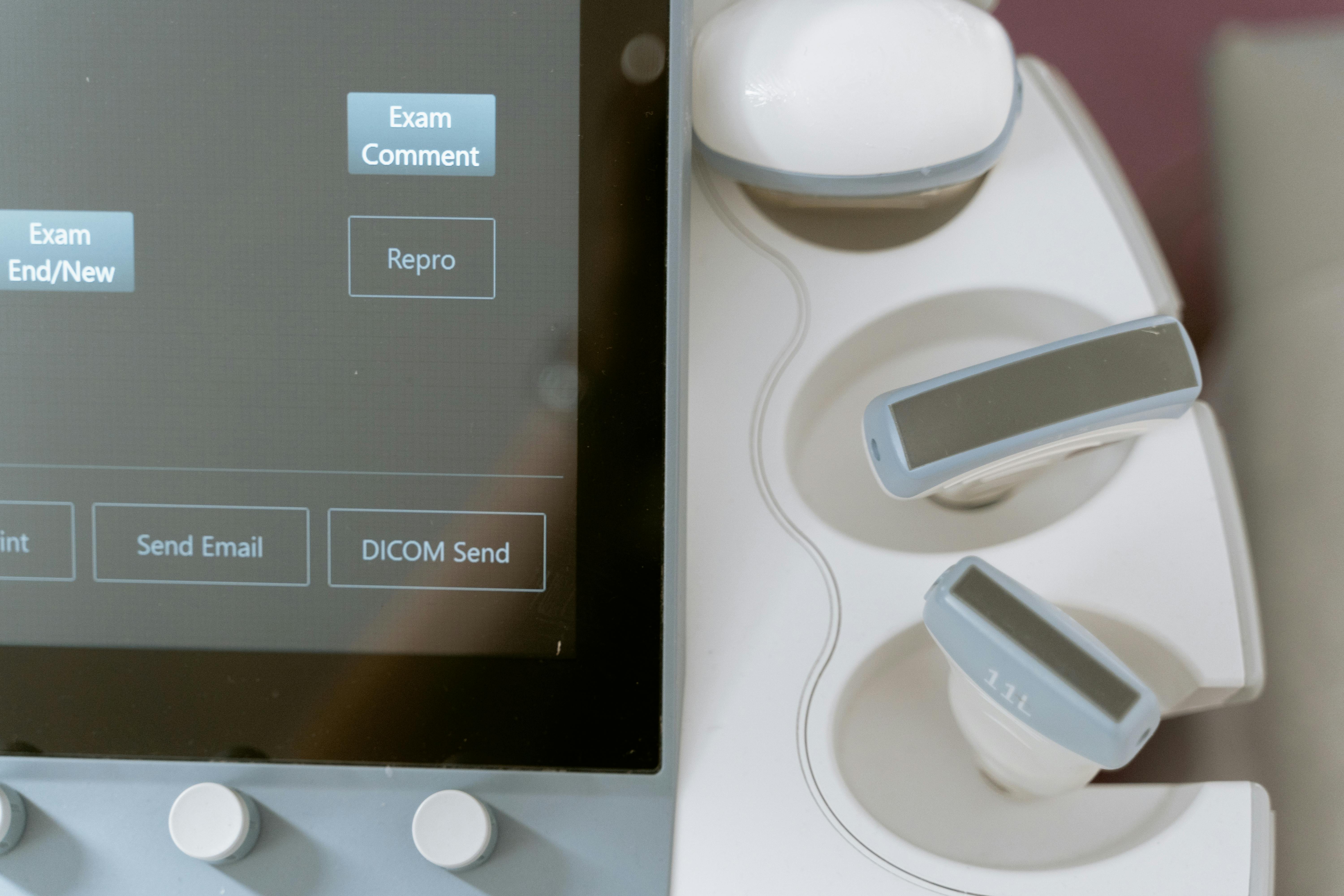
Siemens Ultrasound Needle Guides: Fitment Is Decided by the Probe
A needle guide attaches to the probe, not to the console. Which is why the deciding field on a Siemens needle guide listing names a transducer: a field-by-field read, what wears on the reusable half, and what to send before you order.

3D and 4D Probe Repair: What Fails Inside a Volumetric Probe
A volumetric probe is either a matrix array steered in two axes or a mechanically swept array with a motor and a fluid path. Which one it is decides what fails, what the artifact looks like, and whether a repair route exists.